
About 3 years ago I started experimenting with photogrammetry, since then I have been perfecting a reliable and consistent capture system that fulfilled my goals, trying different techniques and software, to create my first SCANNED 3D MODEL LIBRARY that you can find in the Shop. During this time, lots of people have asked me about the details of the process. In this guide you will find the necessary information for experimenting, on your own, with this interesting technique.
WHAT IS PHOTOGRAMMETRY?
It is a technique that allows us to create 3D models from multiple photographs taken from different angles using specialised software that is able to read perspective variations and create a three-dimensional point cloud.
Photogrammetry has very diverse applications in VFX, video games and 3D in general. It can be used, for example, to scan a real actor and transform it into a digital double that can replace the real actor when necessary.
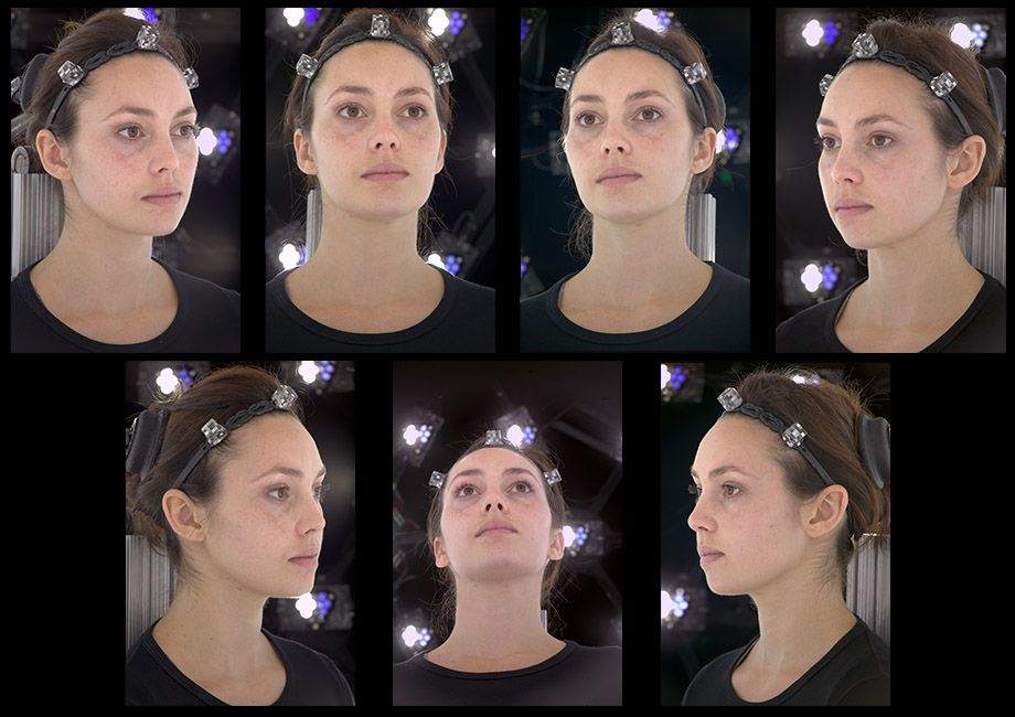 An example of digital double is “digital Emily” that was presented at SIGGRAPH 2008. If you are interested in downloading version 2 of Emily including all the necessary maps you can do it from its official website: http://gl.ict.usc.edu/Research/DigitalEmily2/
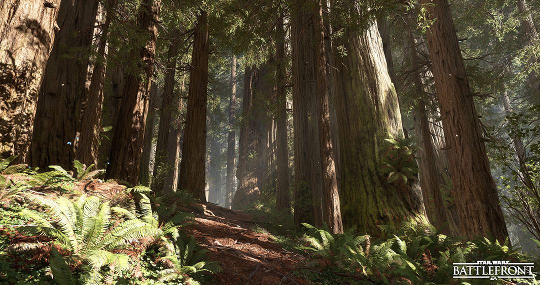
It’s also very often used in video games to scan assets such as rocks, plants, land, surfaces, etc. what allows artists to create a virtual environment much more realistic. A notable example of this technology was the game “Star Wars: Battlefront” where many of the game’s ecosystems were built almost exclusively with models scanned by photogrammetry.
Additionally, photogrammetry has been used for many years in topography and geographic study. The use of drones, has currently made these techniques accessible to the majority.
Another good example of the use of this technology is the work of Sebastian Zapata in Friendly Shade that has taken the scanning of surfaces to the next level.
WHEN TO USE PHOTOGRAMMETRY AND WHEN NOT TO
Although photogrammetry is an excellent scanning technique, it’s not perfect and it is necessary to know it’s limitations before starting to work to avoid problems during the process.
As this technology uses photographs and pattern recognition software to reconstruct the geometry, if our object or surface does not have details or has too uniform patterns, the software will not be able to establish the perspective and therefore the reconstruction of our model can be complicated. An example would be a polished metal object, or a fabric with a very uniform pattern. A possible solution to this problem is to use stickers on our model, or paint it with anti-reflection lacquers or neutral paints in order to scan the surface, but in doing so, we affect the scanning of the texture. For this reason it’s important to plan before making any scan.
PROS
-Relatively easy and inexpensive.
-We get the geometry and the texture
-Very good quality (with the right equipment)
CONS
-It doesn’t not work well on surfaces without variable detail
-It’s difficult to scan metal or glass
-It takes a lot of time and planning
OBJETIVES OF THIS WORKFLOW
- Models with good detail (large and clear photographs)
- Quickness in the capture process (Automate processes)
- Consistency in results (Controlled lighting)
- Good balance between quality / speed / budget
- Lightweight models mainly for use in ArchViz
Before starting to develop a workflow for photogrammetry, it’s important to establish a main objective, to ensure that all the decisions we’ll make along the way, will be destined to meet these goals.
If our goal is the speed of the scan, we’ll use fewer photographs and sacrifice details. If our priority is portability, we’ll have to think about how to scan with a reduced equipment, etc. This step is especially important because it will also condition the necessary equipment for the job. All information in this guide is intended to meet these specific objectives.
NECESSARY EQUIPMENT
Keeping in mind the goals established above, we need the following equipment:
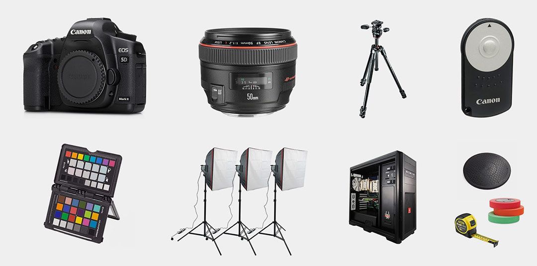
- CAMERA : To achieve the best balance between time spent and details captured we opted for a high resolution camera like the Canon 5DS R of 50Mp that, having no low pass filter, gives us more sharpness. Remember, the more resolution and sharpness, our scanning results will be more accurate will, another interesting alternative could be the Sony A7 r2 42Mp. These cameras are expensive and offer excellent results, but you can use any camera to make photogrammetry.
- LENS: It’s advisable to have a lens that is as clear as possible, in our case we have several high quality Prime 35mm, 50mm and Macro lenses for when it is necessary to scan very small objects. But again if we want to start, it’s possible to do it with whatever equipment we have available.
- TRIPODE Y BALL JOINT: The tripod is an essential piece of equipment that we’ll need to make photogrammetry, since it will allow stability and consistency in the results. In our case we are using a carbon fiber Manfrotto 055 and a Manfrotto 410 Junior Geared ball joint.
- REMOTE SHUTTER: Essential to avoid touching the camera when shooting and to ensure maximum sharpness. I recommend a wireless camera trigger.
- COLOR CHECKER: Essential if we want to achieve a calibrated texture with a correct albedo.
- STUDIO LIGHTS: To achieve conditions that do not depend on the weather, it is advisable to have a set of studio lights that allow us to always scan the same in any situation. In our case we have professional studio flashes. There are economic alternatives of continuous light but given their low intensity, it can affect the photographs sharpness by requiring long exposure times, and their color frequently changes, which can alter the albedo.
- HARDWARE: When making photogrammetry one of the slowest processes is the calculation of the point cloud that the scanning program has to do. This process can take a few WEEKS if you don’t have the right equipment. I recommend a minimum of 64Gb of ram (preferably 128) and if the software supports GPU, as many as you can install. Depending on the quality objectives you have, you can sacrifice hardware.
- OTHERS: It’s also important to have a rotating platform that allows us to standardise the degrees that we’ll rotate before each shot (there are automatic options), tape measure to take measurements and guarantee consistency if we move the camera, gaffer tape, etc.
NOTe: It’s possible to replace the studio flashes with a cross-biased system such as a “ring flash”, but in this document we will only cover what is necessary to scan using large lights instead of cross-polarization. Both techniques have their pros and cons.
REQUIRED SOFTWARE

Once all the necessary equipment has been gathered, it’s the software’s turn . There are 100% free alternatives to perform the photogrammetry process, however, in our case we have decided to invest in certain applications to optimize the results and work more comfortably and quickly.
PAYING OPTIONS
- 3D Studio MAX (248€/month)
- Agisoft Photoscan (From 164€)
- Substance Designer (132€)
- ZBrush (705€)
FREE OPTIONS
- Blender (3D Software)
- MeshLab, Visual SFM, PMVS (Reconstruction)
- xNormal (Texture creation)
- Instant Meshes (Automatic Retopology )
WORKFLOW

We can reduce the process to a series of stages from the capture of photographs, until we obtain our 3D model with materials, ready to be used in our projects. During each of the stages we’ll need to have our goals that were raised at the beginning very present, in order to achieve the desired results.
STEP 1. OBTAINING THE PHOTOGRAPHS
With the aim of obtaining consistent results and good quality , undoubtedly, the most important part of the process is the correct capture of our object’ photographs.
ISO: Since noise can confuse the software during the scanning process, to avoid noise, we generally use the lowest possible ISO allowed by the camera (ISO 100 in our case) .
F-Number: We generally try to use a diaphragm as closed as possible, to increase the depth of field and thus avoid loss of sharpness by defocusing. Values between f8 and f22.
Shutter Speed: Although we are using a good tripod, I recommend using fast shooting speeds to maximise sharpness. Depending on the optics 1/125s for example.
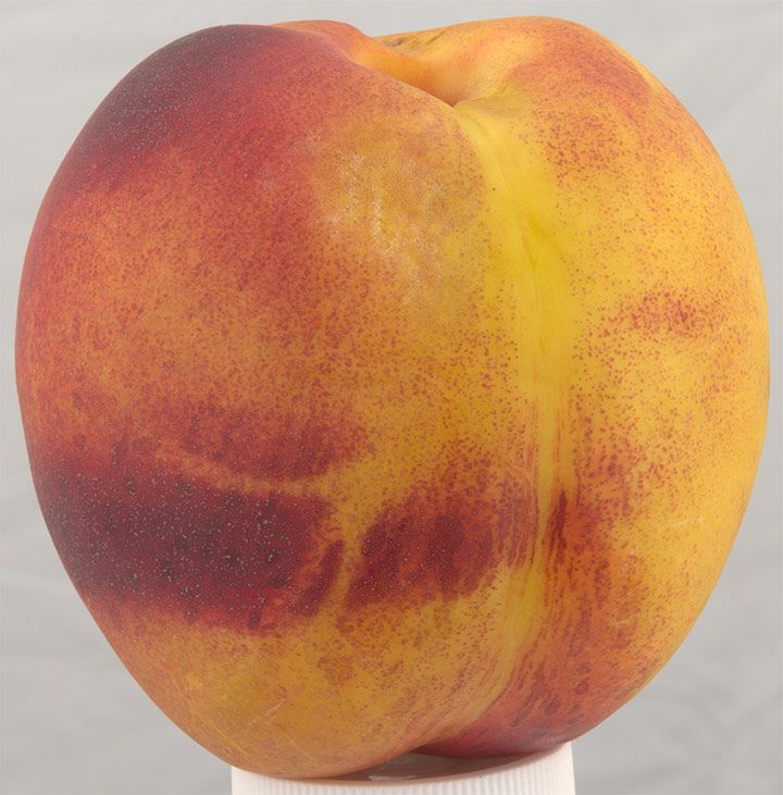
Lighting and background: It’s important to use large light sources located in the front, to eliminate unwanted shadows in our model. In the case of bright spherical objects (such as fruits) it is preferable to use a black background and avoid side lights to neutralize the specular as much as possible.For less shiny objects such as rocks, etc. we can use a chroma, that will facilitate the task of creating the masks later, but on a personal basis I prefer to use a neutral background to avoid contamination and specular. Another alternative would be to use crossed polarization with a “ring flash” or 2 lights located at 45º with respect to the camera.
Number of potos: To obtain good results75-80% of data overlap between photographs is usually necessary. I recommend a minimum of 64 photographs for each complete rotation and it is usually necessary to do 3 or 4 different heights. As a general rule, and to obtain good results, 150-200 photographs are required as MINIMUM per model.
Frame: Each pixel in our picture is useful information that the photogrammetry program can use to add detail, so we’ll always try to fill the frame with our model to waste the minimum amount of pixels possible. If it is a very small objects, we’ll need a macro lens to be able to get closer and focus.
Expousure: To take full advantage of the information contained in the digital negative, you have to try to expose the histogram for highlights without over-exposing important parts of the model.
File format: This is a very important aspect of capturing photographs for photogrammetry. I recommend using the RAW format of our camera to obtain 14-16bpc images that will allow us to later obtain the linear information for our albedo. If we look for an albedo as correct as possible, we will need to create a linear version of our RAW file using for example DCRAW. If the result is too “washed” we can make two versions of our photographs: A linear version to project the albedo textures when completing the process and a more contrasted version to ease the task of the photogrammetry software.
It’s very important to be extremely methodical when taking photographs, for example, we can mark our rotating base to always use the same number of degrees in each position (between 5º and 10º) and always take the photographs in the same order.
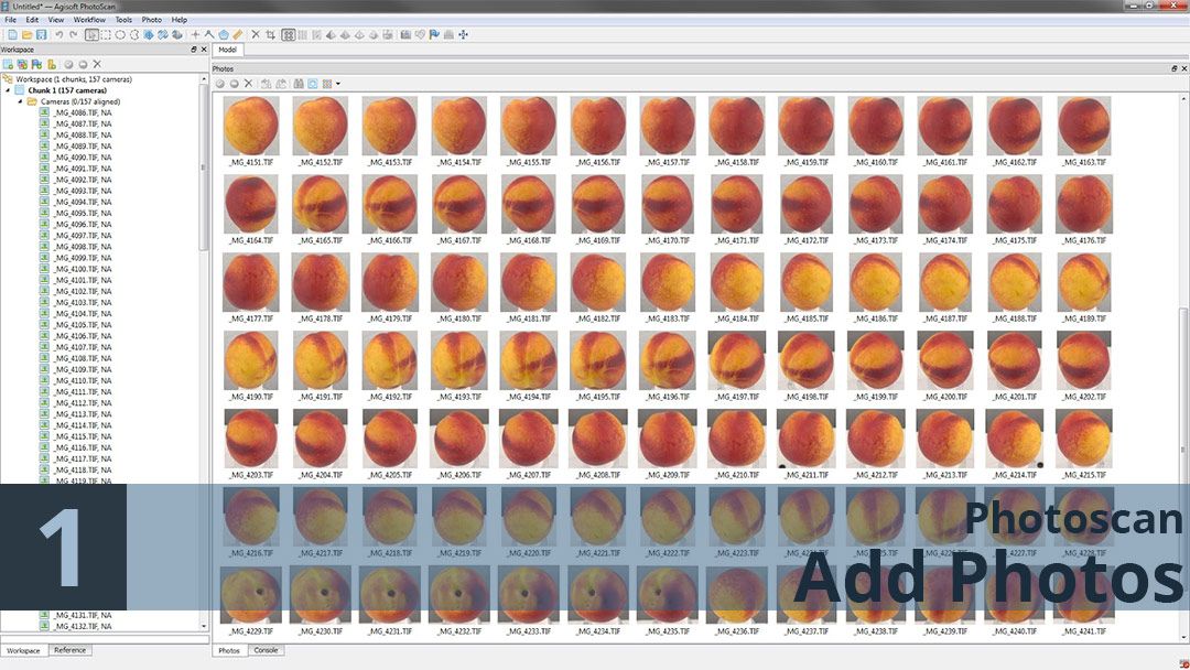
STEP 2. PHOTOSCAN
Once our photographs are captured, upload them in the photogrammetry software to generate our point cloud. In our case we are going to use Photoscan, but you could use the free alternatives mentioned above.
If the process of capturing photographs was done in in a methodical way with conditions of controlled lighting, this step does not require more complication, if the photographs were made by hand or with natural light, it may be necessary to identify the problematic images and eliminate them so they do not damage the calculation.
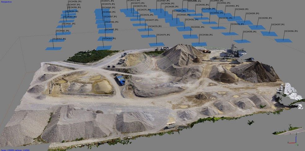
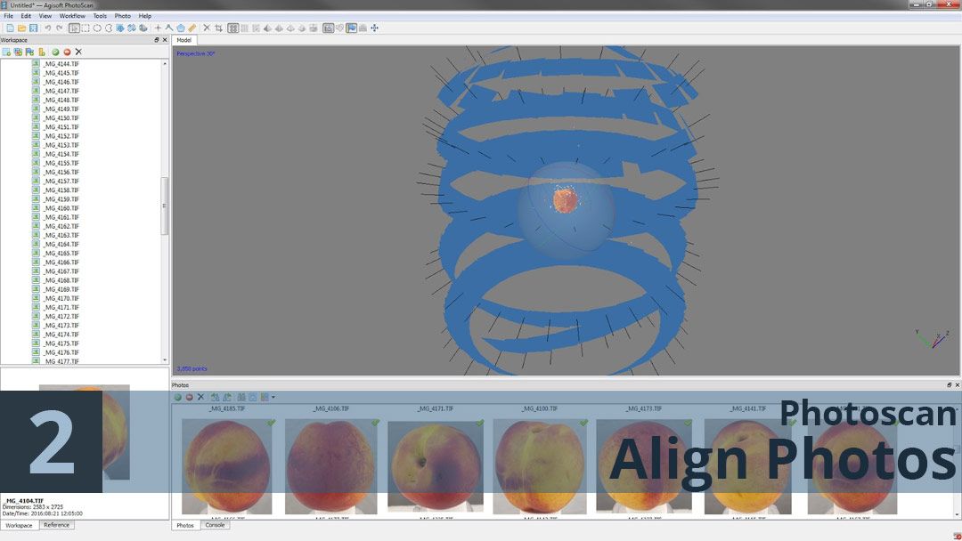
Once our images are loaded in photoscan, the next step is to align them so that the software can calculate the position from which they were taken. At the end, we should have a low resolution point cloud, and an estimate of the position of our cameras as shown in the following image. This phase is ideal to identify possible problems in our photos. If we see that one of our cameras is wrongly aligned, we can eliminate it to avoid problems. And if we see that our point cloud contains many “residual” points, we can eliminate them to speed up the subsequent process.
The next phase of the process is extremely slow and may take days to calculate, so it’s especially important to make sure everything is aligned correctly. One way to prevent the software from having to calculate unnecessary areas to optimize time, is to use masks to eliminate the background from the equation. We can do this manually, by rotoscopy, by difference or with Chroma Key in software such as After Effect and load our mask with “_MASK” so that photoscan can recognize it automatically. There is also the possibility of using the low-resolution geometry previously calculated as a mask.
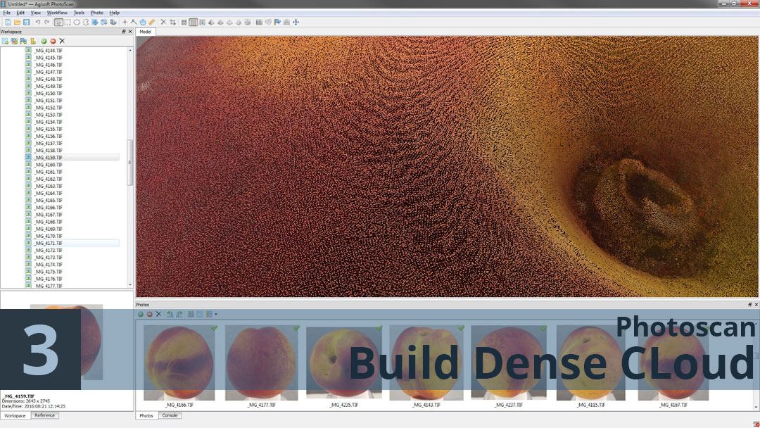
Once the process is completed we will have a very high density point cloud, with millions of points that represent the three-dimensional position of each of the vertices calculated during the previous process, but these points still do not define a three-dimensional geometry, they are simply points in space. To generate our polygonal high resolution geometry, we will use the photoscan option Workflow > Build Mesh
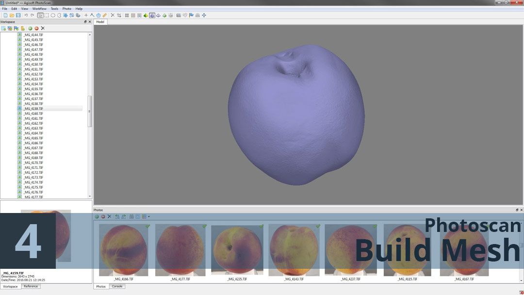
We’re getting there!. With this we already have a high resolution 3D model that faithfully represents our original object, but we still have a lot of work ahead of us. Now it is necessary to map out the photographs on this geometry, luckily this is a very fast process because photoscan has already calculated the position of each camera and simply has to map out the images and generate a texture. At this point, we can change our contrasted images by our linear textures obtained with DCRAW to ensure a correct albedo.
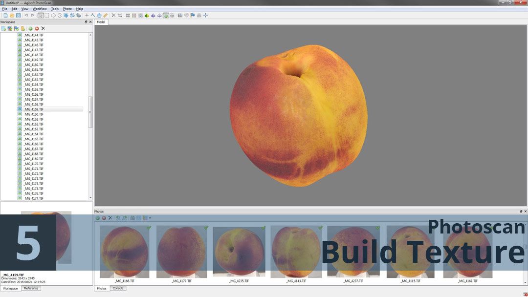
Once the process is finished we’ll have our 3D model and our linear textures applied on automatic mapping coordinates created by Photoscan. Ok so it’s taking shape, but this model is not yet ready to be used in production, we are talking about a model with millions of polygons and automatic mapping coordinates, that it’s very difficult to manage, in addition, photogrammetry software is not usually able to correctly represent completely polished surfaces, so it’s usually necessary to work to correct the model in Zbrush. In part 2 of this guide you will discover how to transform this high resolution model into a more manageable model and how to transfer height and albedo information to new manually created mapping coordinates.
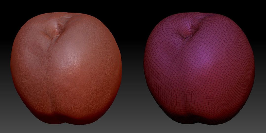
STEP 3. RETOPOLY
The first step to optimize our model for use, is to considerably reduce the number of polygons maintaining it’s structure and silhouette. This task can be done in many ways; in this video (i’m sorry is in spanish) I explain how to do it manually in 3D Studio MAX. One of the most interesting options for this part of our workflow is ZBrush that has several automatic tools like ZRemesher that can save us a lot of work and offer excellent results for organic objects. An automatic free alternative for this process is Instant Meshes
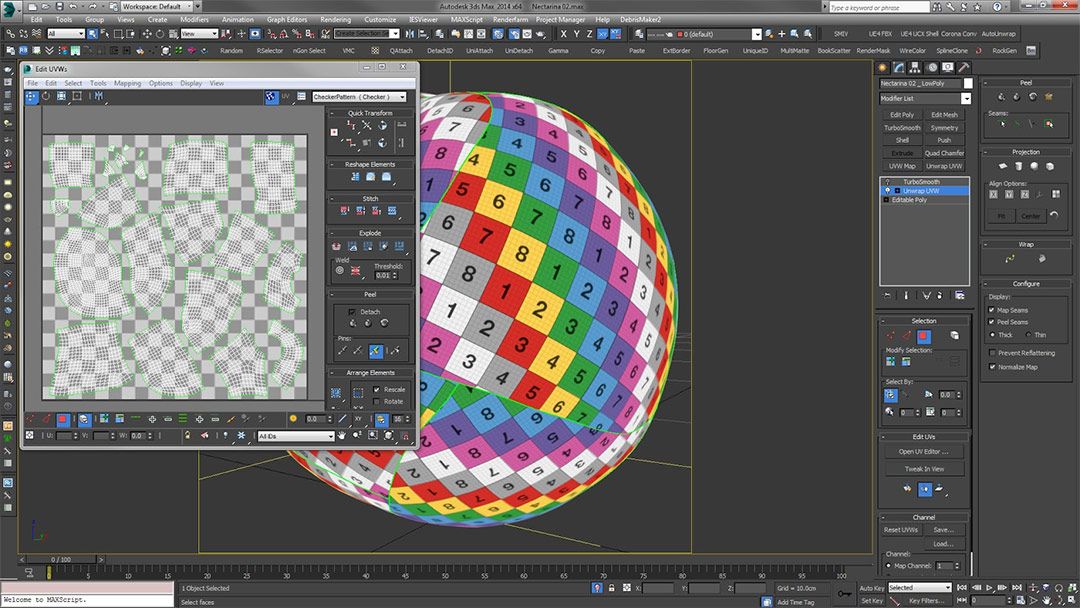
STEP 4. CREATING UV MAPPING COORDINATES
We are one step closer to our final result, but for now, our new low resolution model does not have mapping coordinates or textures. In order to transfer the details of our original model and the albedo to our low resolution model, we need new mapping coordinates. This work can be done directly in ZBrush with the UV Master tool or in another application such as 3D Studio MAX or UV Layout. In this video (again, sorry is in spanish) the process of creating mapping coordinates in 3D Studio MAX is explained in detail.
STEP 5. TEXTURE CREATION
We already have our high resolution model with texture and our low resolution model with new mapping coordinates. The next step in the process is to use the information from our high resolution model to create new maps for the optimized model. This task can be done with multiple applications such as xNormal, ZBrush itself, etc. In our case we preferred to use Substance Designer because of it’s easier,, because it offers excellent results, and for the possibility of automating the process in multiple models at the same time.
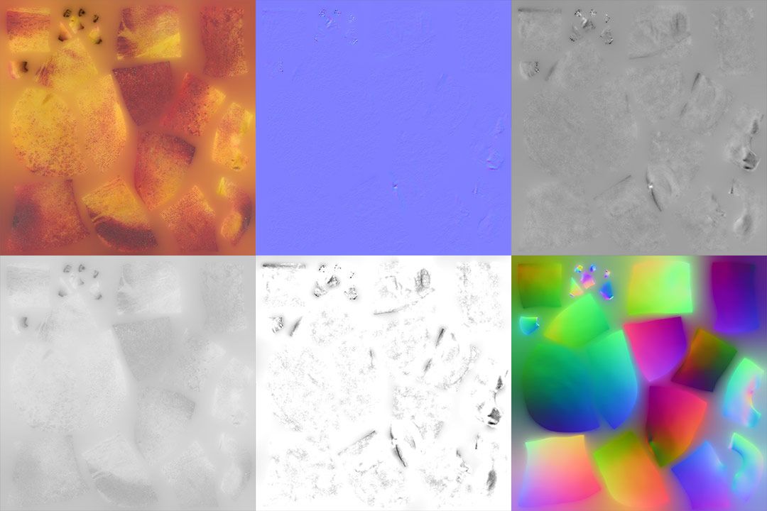
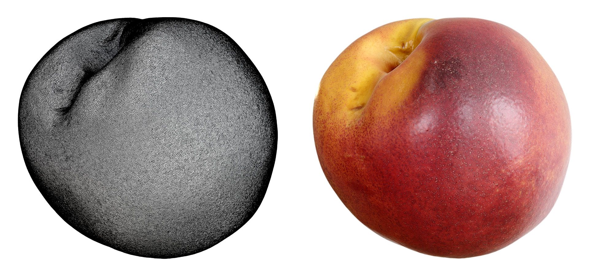
Albedo: It’s the texture generated by Photoscan projected on the new mapping coordinates.
NormalMap: Contains the height information of the high-resolution model in the form of normal maps.
Linear Displacement: Height information of the original model in grey scale.
AO/Curvature: Useful to add “artificial” volume to our texture, it can be interesting in video games.
Local Normal: local Normal map that can be useful for manual delighting if necessary.
Glossiness: In our case, this map is obtained manually using a combination of albedo, height and reference photographs.
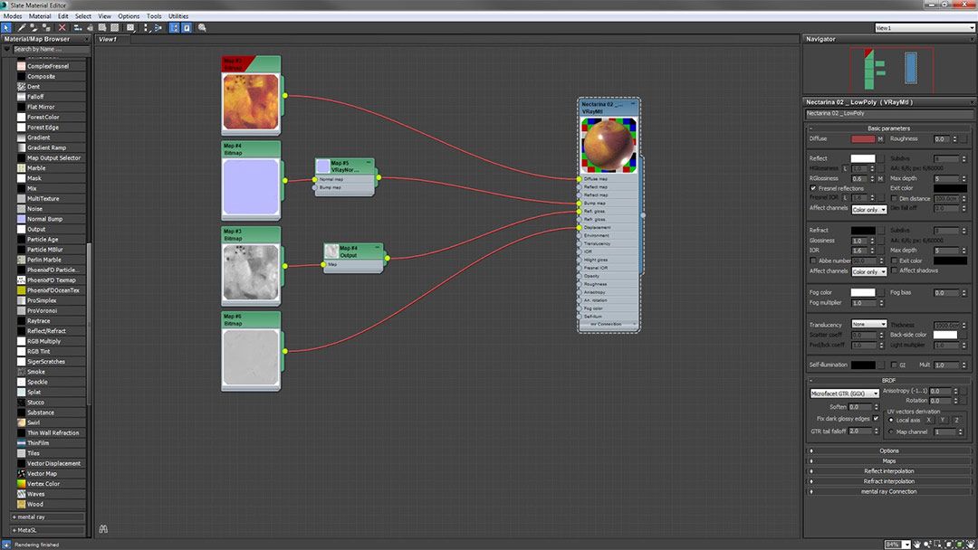
STEP 6. PBR MATERIALS CREATION
Finally, with the low resolution 3D model and the textures generated in Substance Designer, we have everything necessary to complete the process and create our PBR materials. To guarantee the best results, I recommend taking photographs of the real model in easy-to-reproduce lighting conditions for reference.
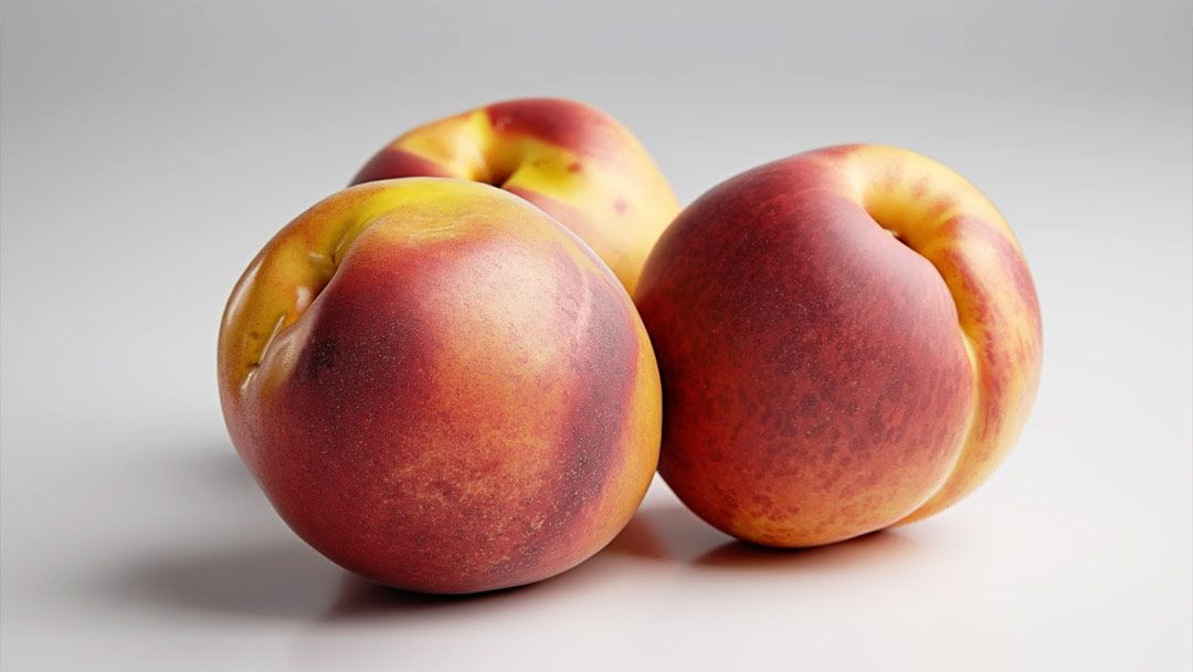
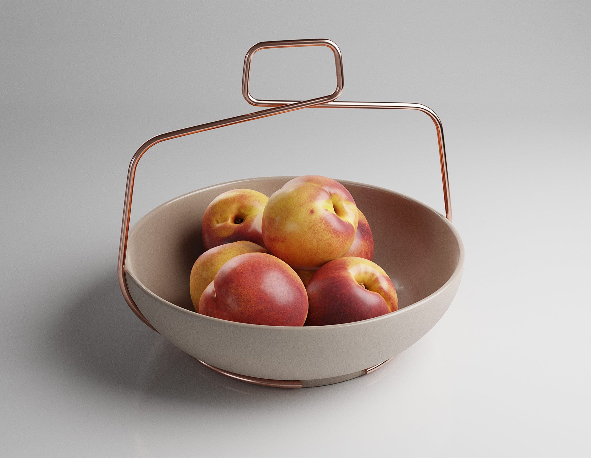
This is the final result rendered in 3D Studio Max and V-ray:
FINAL THOUGHTS
- Planning is the key to obtaining good results.
- Good lighting and methodology simplify the process.
- Getting good results require a lot of time and dedication.
- Photogrammetry is not perfect, but it is a good starting point.
- The quality of the equipment can improve the result.
NOTE: This is article was written by me with the help of google translate. As you know , English is not my first language. So if you find an error on the grammar or the in the way that ideas are exposed, please let me know in the comments bellow so that i can correct it as soon as possible. We are all learning here! 🙂